KNOWLEDGE CENTER
LEDs vs. Lasers, Why Use LEDs
Laser light is unique, in that it is monochromatic, coherent, and collimated. These traits make it well-suited to many applications. However, lasers can exhibit some significant disadvantages. Diode lasers are prone to mode hopping and back reflections, both behaviors can cause instability in power and wavelength. Diode pumped solid-state lasers (DPSS) are instable during TTL modulation. All lasers exhibit speckle noise, a property of coherence which requires intricate optical methods to eliminate. Lasers are not suitable for wide field fluorescence microscopy. The thin collimated beam from lasers is difficult to expand.
LEDs are efficient and small like laser diodes but typically LEDs operate at lower drive currents with low heat and longer life. LEDs are available in a multitude of peak wavelengths while lasers have fewer wavelength options. When fiber optic delivery is desired, LEDs are optimum for their convenient size, affordable price range, and high radiance. LEDs are most appropriate for multi-mode fiber and relatively shorter cable runs. In scientific applications such as fluorescence excitation or photoactivation in optogenetics, the LED is operated with constant current and the ON/OFF switching is controlled through an external TTL input, or internal digital trigger.
Coupling Light from an LED into an Optical Fiber
A laser can emit a thin collimated beam, or at least one of low divergence such as in semiconductor diode lasers or VCSELs (vertical cavity surface emitting lasers). To understand the light propagation from a non-coherent surface emitter like an LED and how to estimate fiber optic coupling efficiency, one must understand the optical concepts of a Lambertian source and the radiometric quantity “radiance” for the LED; as well as the specification of numerical aperture (NA), and the definition of étendue for the optical fiber.
Lambertian Emitters
A Lambertian source plane is an ideal diffuse emitter or reflector. It looks equally bright from all directions. It emits or reflects a radiant intensity (flux per unit solid angle) that is proportional to the cosine of the angle from the surface normal. Matte white paper and excited phosphors are approximate examples of such source planes, as is the flat emitting surface of an LED die.

Figure 1
The light emanating from the surface of a Lambertian emitter is best described by its radiance, the radiant intensity emitted from a known unit area of a source. Radiance is an important engineering quantity since it is used to predict the amount of flux that can be collected by an optical system that would view the emitting surface especially when the system’s field-of-view solid angle is over-filled by the Lambertian source.
The radiance of a Lambertian emitter, L, emitting total radiant flux in all directions, Φ (mW), is given by;

Where A is the total surface area of the source (m2) and π steradians (sr) is the projected solid angle from the surface.
While the cosine law, Figure 2, holds for the radiant intensity (mW sr-1) in different directions, being Lambertian also means that the source radiance L is independent of view angle.

Total radiant flux, Φ, is a common specification provided by LED manufacturers at a specific drive current. In this discussion, the LED can be assumed to be a single die like in Figure 1. The area A in Equation 1 is the emitting area of the LED die, typically 1mm x 1mm.

Figure 2
Fiber Optics
Optical fiber uses the optical principle of “total internal reflection” to capture the light transmitted in an optical fiber and confine the light to the core of the fiber. An optical fiber is comprised of a light-carrying core in the center, surrounded by a cladding that acts to trap light in the core. The cladding usually is made of the same material as the core, but with a slightly lower index of refraction (usually about 1% lower). This index difference causes total internal reflection to occur at the index boundary along the length of the fiber so that the light is transmitted down the fiber and does not escape through the sidewalls. The following diagram, Figure 4, shows a “step Index” optical fiber which is most commonly used with LEDs. Another property for a fiber with an LED is that it be considered “multi-mode” which means a core diameter ≥ 50 micrometers.

Figure 4
Numerical Aperture (NA) of an Optical Fiber
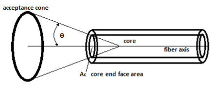
There is a critical angle that for any given optical fiber defines total internal reflection. At higher angles a ray of light will still be refracted but not enough to be reflected back into the core, so it is lost in the cladding of the fiber. Below that angle, it will be reflected back into the core of the fiber and transmitted to the end of the fiber. The angle of total internal reflection defines the “numerical aperture” (NA) of the fiber, a standard optical fiber specification. Numerical aperture (NA) is the measure of the maximum angle at which light rays will enter and be directed down the fiber. This is represented by Figure 4 above and the following equation:
Étendue
Étendue describes the ability of a source to emit light or the ability of an optical system to accept light. It is a property of an optical system, which characterizes how “spread out” the light is in both area and angle. From the optical system point of view, the étendue equals the area of the entrance pupil times the solid angle the source subtends as viewed from the pupil. Étendue is one of the most basic yet important concepts in the design of non-imaging and illumination optics. Firstly, it explains the flux transfer characteristics of the optical system, and secondly, it plays an integral role in the ability to shape the distribution of radiation at the target. The smallest étendue in the overall optical system limits the maximum possible light flux throughput.
Étendue of an Optical Fiber
For an optical fiber, the area of the entrance pupil is based on the core diameter;

Figure 5
The projected solid angle of the acceptance cone is;
For a single strand fiber, Ac is the area of the fiber end calculated for the core diameter. Multiplying Equation 5 by the area of the core end-face provides the etendue (G);
Radiant Flux Transmitted by An Optical Fiber


Figure 6
The total flux emitted from the fiber has additional loss factors such as the Fresnel reflectance losses at the air/fiber interface for both ends of the fiber and the core material extinction coefficient (cm-1) along its length (cm) of an optical fiber cable which is due to;
Rayleigh scattering from microscopic-scale variations in the index of refraction of the core material. This is the most important loss mechanism in modern optical fibers, generally accounting for up to 90% of any loss that is experienced.
Absorption — Optical fiber production methods have reduced absorption caused by impurities (most notably water in the fiber core) to very low levels. Within the spectral range of transmission for the fiber, absorption losses within the core are insignificant.
Bending —Bends in the fiber geometry sometimes will be great enough to cause the light within the core to traverse at less than the TIR critical angle inducing absorption by the cladding material. This also occurs when the fiber is bent in a tight radius (less than a few centimeters).
Comparing Flux Emission Between Different Optical Fibers
Manufacturers of fiber-coupled LEDs often specify the total radiant flux in mW emitted, but they also must indicate the NA and core diameter of the optical fiber used. This is because of Equation 6, the fiber étendue which includes both factors. The Fresnel losses and internal transmission are accounted for in the measured flux value. If one needs to estimate the total flux from using a smaller core fiber than specified of the same NA, the relative coupling efficiency Fc is a factor of the ratio of core areas, and therefore the ratio of the core diameters squared.

Where d0 is the core diameter used in the manufacturer’s specification and d1 is the smaller core fiber to be coupled by the end user. In addition, if the NA of the user’s fiber is smaller than originally specified, the ratio of the projected solid angles is another major factor for relative coupling efficiency, and it is given by the ratio of the NAs squared. The overall coupling efficiency is given by;

As long as the two fibers operate within the same spectral window, Fresnel and internal losses are insignificant for a first order approximation.
Example:
D0 = 1.0 mm and NA 0 = 0.63 with total flux emitted specified as 200 mW.
The relative coupling efficiency when substituting an optical fiber of D 1 = 0.6 mm and NA1 = 0.50 is;

The total flux from the 600 mm, NA 0.5 fiber would be 45.3 mW, 22.7% of 200 mW. Any increase in power would require increasing the radiance of the LED accomplished by careful overdriving at constant current constrained by avoiding the maximum drive conditions of the LED, and proper thermal management of the LED junction temperature.
